Manufacturing process and structural design of automotive body stamping parts
In the process of automobile body manufacturing, body stamping and welding parts are the main research objects, and their manufacturing dimensional deviations directly affect the quality of automobile products, such as sealing, wind noise, service life, power performance, and appearance. Testing the stamping and welding parts of the car body is an important means of its quality, and at the same time, the testing of stamping and welding parts of the car body is a complex process. As a tool for testing the quality of products between processes, the inspection tool plays a role in checking the manufacturing quality of stamping parts, components, sub assemblies, and assemblies at all levels, and is a key factor in the quality of car body manufacturing. Therefore, it is of great significance to design stamping and welding parts inspection in a reasonable and efficient manner.
1. Overview of the definition of measuring tools
Inspection tool is a three-dimensional measuring tool used for the inspection of automotive stamping and welding parts. It can eliminate the use of conventional measuring tools such as calipers, rulers, and block gauges, and can achieve accurate, intuitive and precise inspection of automotive components with only a go stop gauge or gap gauge. According to the measurement object, it can be divided into assembly inspection tools and component inspection tools. It mainly consists of a detection mechanism, a positioning mechanism, a clamping mechanism, a support mechanism, a fixture base, and other auxiliary parts. At the production site, the parts are accurately installed on the inspection tool, and then the surface and various hole positions of the parts are inspected through inspection pins, marking pins, through and out gauges, visual inspection, measuring gauges, calipers, gap gauges, etc., in order to judge the quality status of the parts. In the automotive industry with large-scale assembly line production, the application of gauges has become quite common, especially for automotive body stamping and welding parts.
2. Characteristics of Inspection for Automotive Body Stamping and Welding Parts
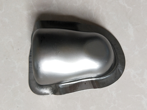
(1) The shape of the workpiece is often complex, with many curved surfaces and irregularities, making it difficult to locate, support, and clamp;
(2) The stiffness of the workpiece is poor, and errors are easily caused by deformation during the detection process;
(3) Except for a few stamped parts, the dimensional reference of the workpiece is usually placed in the vehicle coordinate system for processing;
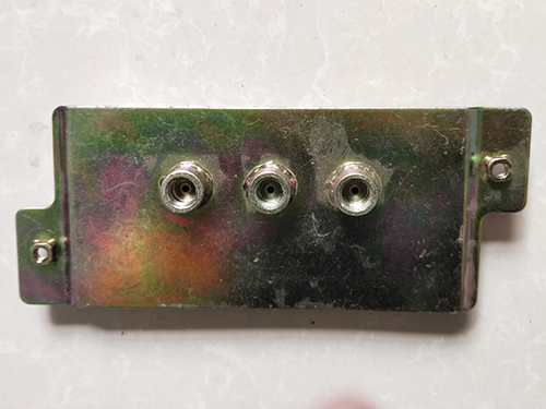
(4) Large batch size, high precision requirements for matching surfaces and hole positions.
The inspection tool for automotive body stamping and welding parts can be roughly divided into four stages: scheme design stage, structural design stage, manufacturing and debugging stage, and verification and approval stage. The manufacturing and debugging stage refers to the general manufacturing process of production based on the technical specifications of three-dimensional numerical models, two-dimensional drawings, and inspection tools, which will not be discussed here.
Structural design of 3 stamping parts inspection tools
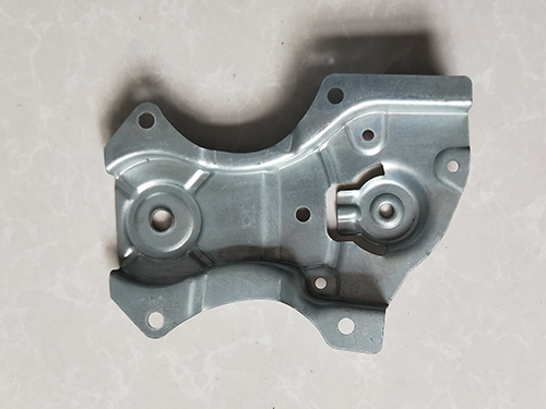
For body stamping parts, since the detection elements include the contour of the workpiece, the shape of the curved surface, the position of the holes and protrusions, especially the shape of the curved surface, the support mechanism often adopts the method of integral surface, and then is equipped with positioning surfaces, positioning pins, detection guide holes, detection pins, clamping devices, section detection plates, etc.
3.1 Refined design of the base part
After the preliminary completion of the above design, the base plate will be assembled for detailed design of the base part. The main steps are:
1) Assemble the product in a coordinate system and determine the base plate plane based on the positioning and operating height of the inspection tools established during the design phase;
2) Offset the surface of the product to be tested outward by 3mm to form a detection surface with a profile (if it is necessary to detect the contour cutting line of the product, the offset detection surface needs to be extended outward along the normal by 20-25mm);
3) Stretching along the contour edge towards the plane where the base plate is located, forming a profile;
4) After detailed processing, make inspection holes and assemble reference surfaces, reference positioning pins, clamping devices, inspection cards, etc;
5) Assemble the pre designed base plate and refine the design of the base plate based on the design of the upper profile;
6) Assembling measurement benchmarks, lifting ears, engraving hundreds of lines, etc;
7) Design and manufacture small carts according to the operating height for storing and transferring inspection tools;
8) Inspect the design, refine it, complete the 3D design of the gauge, and draw 2D drawings.
3.2 Design elements of gauge base plate
In the design, the design of the fixture base plate plays a very important role in the stability of the entire fixture. When designing, the following aspects can be considered:
1) Prioritize the use of cast aluminum base plates when costs permit;
2) Welding the base plate requires stress relief treatment (usually tempering treatment);
3) Using steel plates and channel steel for welding, cross structure and meter shaped structure are currently the two commonly used structures;
4) The size of the base plate should be such that each part of the gauge does not exceed the gauge in any of its active positions;
5) Lifting lugs and forklift slots should be designed on the bottom plate of inspection tools with a net weight exceeding 22kg. The design of the lifting ear should consider a large bearing capacity and ensure that the lifting rope does not affect the shape of the measuring tool, functional components, and all measuring elements during lifting, and can maintain balance during lifting. The design of forklift slots should consider the larger load-bearing capacity and the specifications of ordinary forklifts; Small gauges with a net weight less than 22kg should be equipped with handles.