A Brief Discussion on the Relationship between Punching Gap, Stamping Part Quali
1 Introduction
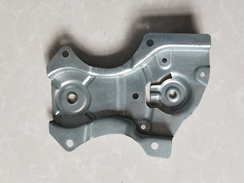
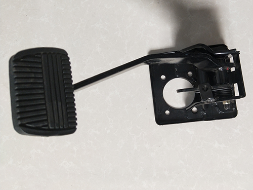
The blanking die and punching die are a type of punching that separates one part of a material from another along a closed contour. The reasonable gap between convex and concave molds is essential for automotive metal stamping parts; The key to quality and die life.
2. Punching clearance and stamping part quality
The punching gap is too large for the stamped parts; If the burrs are too large, even if the punching gap is too small, burrs will appear on the stamped parts. The numerical value of the gap is closely related to the thickness and properties of the material. Currently, there is no accurate theoretical calculation formula, and it is often determined through theoretical calculations, experiments, and reference to relevant data.
During the punching process, the metal being punched undergoes plastic deformation, and the material in the gap area flows radially over the convex and concave die edges, generating viscous friction and mainly causing wear on the end face of the die. The friction coefficient at the edge is relatively high, resulting in faster wear. When the gap increases, due to the bending of the material, the contact surface between the die end face and the material decreases, resulting in an increase in the peak stress at the cutting edge, exacerbating wear and making the cutting edge blunt. In addition, the stamping die also has side wear, which is mainly caused by the sliding friction of the separated material (stamped parts or waste) during the unloading (pushing) process, in addition to the lateral compression of the material during the deformation process. For each part punched, the punched part tightly clamped on the convex mold slides back and forth twice along the side of the convex mold. When the punched part is pushed out of the punch, the material and punch gradually change from surface contact to line contact, resulting in faster wear of the cutting edge. For concave molds, if the falling part is a falling type, it will experience friction from the falling part every time it is punched, because the falling part is often looser than the punching part, so the wear of the cutting edge is milder than that of the convex mold. If the concave mold has a conical blade, the blade wear will be faster. Of course, if the falling part is a top out structure, the wear of the concave mold is similar to that of the convex mold. Obviously, for the formation of burrs, side wear has a greater impact than end wear.
As is well known, the size difference between stamped parts and stamping dies varies with clearance. The smaller the clearance between the convex and concave dies, the larger the size of the stamped part, and the larger the clearance between the convex and concave dies (within a certain range), the smaller the size of the stamped part. According to relevant records, taking the example of punching a 1.5mm thick brass plate, when the gap exceeds 25%, the punching size is larger than the convex mold size, and when the gap is greater than 9%, the cutting size is smaller than the concave mold size. Obviously, by selecting a gap value greater than the above, there will be no sliding friction between the stamping part and the side of the die, and the resulting wear will be eliminated. During the working process of the die, there is basically no need for unloading force and pushing force. When selecting a clearance smaller than the above, the smaller the clearance, the greater the interference fit, and the more severe the wear. The plastic shear band of stamped parts decreases with the increase of clearance, and the pressure area on the die also decreases, thereby reducing side wear. From this, it can be concluded that, under the condition of acceptable stamping quality, the gap value between the stamping part size and the die size is the optimal gap, and the die life is higher. If it gets bigger, it will increase the end face wear of the stamping die and the quality of the stamped parts will decrease. If there is a concern about the quality of the stamped parts, a smaller gap can be taken, but it should not be too small as much as possible to control the wear on the side of the die.
In production, it is often found that the gap between the punching dies becomes larger as they are punched. In order to increase the allowable number of blade grinding times, the initial small gap is always used in the design of metal stamping parts to prevent the gap from entering the burr growth zone too quickly. In fact, the increase in gap is precisely caused by small gaps (note: there are also other factors that can cause it, which will not be analyzed here). Taking the convex die as an example for analysis, if the convex die extends into the concave die by a material thickness t when the die is closed, the punched part (or waste hole) slides within the 2t height range of the convex die. Due to severe side wear, the size of the convex die gradually decreases, and only the obtuse angle part is ground off during grinding. Similarly, the size of the concave die gradually increases, and when the gap exceeds the limit, as mentioned earlier, even if the cutting edge is sharpened, burrs will appear too long and the die will have to be scrapped. In order to reduce die wear and prevent falling parts from blocking the cavity of the concave mold, a conical concave mold blade (falling type) structure is usually used. However, this not only accelerates the wear of the concave mold blade, but also increases the size of the concave mold cavity. If a larger gap is appropriately used in the design to reduce side wear to a lower limit, the dimensional changes of the convex and concave molds after prolonged use are also extremely small.
Practice has proven that appropriately increasing the gap can delay the occurrence of blunt angles at the cutting edge of the die and double the number of stamped parts between the grinding edges. Due to the fact that the side of the convex concave die is basically not subjected to the pressure of separated stamping parts and waste parts, there are many advantages as follows:
(1) Preventing mold sticking and reducing lubrication, mold sticking is caused by severe friction and heat generation. The rough cutting edge of the die after sticking causes burrs to be pulled out from the cross-section of the stamped part. Severe exacerbation of wear and tear.
(2) Stamping parts are no longer blocked in the concave mold cavity, so a straight edge concave mold can be used, which increases the die edge and improves the utilization rate.
(3) The side of the convex and concave dies processed by wire cutting electric discharge machine has a brittle superhard layer of about 0.1mm. If the die hardness is 62HRC, the superhard layer can reach 68HRC, but there is also a soft thin layer with a hardness below 60HRC inside the superhard layer. Appropriately increasing the gap reduces wear, protects the superhard layer, and further improves the lifespan of the die.
(4) The thickness and wall thickness of the concave mold can be reduced, and the design of the concave mold is mainly based on strength calculation. Usually, considering that multi-layer workpieces (waste materials) are tightly packed in the cavity of the concave mold, the recommended thickness and wall thickness in the data are relatively large, and the tangential tensile stress on the concave mold is proportional to the tension P. After appropriately increasing the gap, there are no other radial forces except for the radial compression of the material during the punching process. The reduction in the size of the corpse has been significantly reduced, resulting in a decrease in the wall thickness and thickness of the concave mold. This not only saves expensive mold materials but also reduces processing time, especially for processing equipment, demonstrating significant economic benefits.
(5) It can avoid the phenomenon of easily occurring concave mold expansion and cracking.
(6) When the block concave mold adopts a falling structure, the compressive tension inside the cavity is high due to the stress conditions of the block concave mold. The more accumulated parts in the mold cavity, the greater the tension, and the mold cavity is prone to forming a conical shape, making it difficult for stamped parts to fall. Therefore, it is generally recommended to embed the block concave mold deeply into the bottom plate, and it is not advisable to use a falling form. By appropriately increasing the gap, the structure of the punching die can be improved to make the entire structure of the punching die more reasonable.
(7) Reduced the phenomenon of 'blade biting'. At the same time as completing the punching deformation, the punch also needs to bear the additional load of pushing out the workpiece. The more stamped parts accumulate in the cavity, the greater the additional load on the punch. When the convex mold undergoes unstable bending due to excessive force, it will produce the phenomenon of the convex concave mold biting the edge. In general, in the design of stamping dies, when checking the strength of the punch, only the punching force is considered and the additional pushing force is ignored. For automotive stamping parts, the problem is prominent when the punch is slender. By appropriately increasing the gap, it is possible to add additional pushing load.
(8) Reduced unloading force, avoided large elastic unloading devices, and facilitated operation.
(9) After the use of the punching die, the size of the convex and concave dies does not change much, making it easy to control the dimensional accuracy of the stamped parts and the quality of the stamped parts.
(10) Reduced the total punching force.
It can be seen that all the above advantages are brought about by the just right gap. However, it should be noted that the clearance between the convex and concave dies should be uniform during the punching process to prevent material carryover (the stamped part being carried out of the concave die edge by the convex die). When designing the stamping die, it is recommended to use a guide column and guide sleeve structure as much as possible. Joint guidance should be used for the slender convex die to prevent instability and deformation, improve the rigidity of the lower base plate, and prevent deformation of the heat-treated parts as much as possible. The overall parallelism and perpendicularity of the stamping die should meet the assembly requirements in order to achieve the desired effect.