Design method and processing operation precautions for stamped parts
Stamping parts are closely related to the car body, and the design method of the car body is the design method of stamping parts, because the purpose of car body design is to design structurally reasonable automotive hardware stamping parts that can be welded into a white body;, And it has good formability and is easy to mold.
In the process of stamping parts; When designing, the basic dimensions of stamped parts need to be determined based on known conditions. For large stamped parts such as door panels, engine hood panels, and side panel panels, the basic dimensions need to be determined based on the numerical model of the vehicle body cover. For some reinforcement plates, the basic dimensions need to be determined based on the required reinforcement position, welding position, and other conditions. For installation plates, the basic dimensions need to be determined based on the location and welding position of the installation parts; After the basic dimensions are determined, it is necessary to define the curved surface style of the stamped parts. The curved surface form of large stamped parts such as car door inner panels is determined based on the outer panel, which is basically a design process from the outside to the inside. When designing these large stamped parts, it is necessary to consider the factors such as the cross-section, hard points, cavities, ventilation, vibration, etc. formed between the outer panel and the inner panel. The curved surface of the strengthening plate is determined based on known conditions such as strength and strengthening parts, and the design freedom of the installation plate is relatively high; Details on later stamped parts, such as reinforcing ribs, protrusions, holes, etc.
1. Determination of basic dimensions
The difference between the engine hood and other stamped parts is that the engine hood is usually stamped as an assembly, that is, the later process of the engine hood mold is to form the outer and inner panels into a whole, and the engine hood is not assembled on the body through welding. Instead, after the white body is welded, it is installed with the body through hinges on the adjustment line. The outer panel of the engine hood usually has a circle of edge pressing at the edge. The edge of the inner panel of the engine hood is embedded in the edge pressing through a mold, and then the outer and inner panel edges are compressed and connected together through some reinforcement methods to form an assembly. It can be seen that the basic size of the inner panel of the engine hood is determined by the outer panel, and the size of the outer panel of the engine hood is basically used.
2. Determination of surface form
According to the structure of the engine hood, the curved surface of the engine hood inner panel is mainly composed of three parts: 1. The curved surface of the inner panel at the edge of the engine hood outer panel, which is mainly used to embed the edge of the engine hood outer panel and form an engine hood assembly; 2. The curved surface of the engine hood inner panel at the hood lock is mainly matched with the curved surface of the stamped part at the hood lock; 3. The basic surface of the engine hood inner panel is mainly offset by the surface of the engine hood outer panel in order to achieve a beautiful appearance of the engine hood assembly. All future detail modification work will be completed on this basic surface. It should be pointed out that both the inner and outer panels of the engine hood are symmetrical, and only half of the curved surface needs to be made during design, while the other half can be mirrored.
3. Details of
The engine hood is an extremely important assembly and often needs to be opened and closed. Therefore, when designing the engine hood inner panel, metal stamping parts should be designed with some gaps to reduce the weight of the engine hood: when the engine hood assembly is formed, several cavities will be formed in the middle, filled with some shock-absorbing and sealing materials, and the cavity needs to be sealed around it. Therefore, some flanges are needed around the cavity to reduce the distance between the inner and outer panels and facilitate sealing. It is necessary to improve the strength of the engine hood by machining some reinforcing ribs on the inner panel. The engine hood inner panel should be fixed with some hose buckles for the engine compartment, hoses and nozzles for washing liquid, and components for the hood lock. A decorative crossover strip needs to be installed at the front end of the hood, so some holes need to be machined in suitable positions on the inner panel. Due to the frequent opening and closing of the engine hood, a protrusion needs to be machined on the inner panel to place the hood buffer block.
After the stamping part design is completed, a series of checks need to be carried out to analyze whether the stamping part meets the initial design conditions, whether it meets the stamping and usage conditions of the stamping part, and whether it is assembled properly without interference in the later stage. Based on this, optimization design of the stamping part is carried out to ensure the design of the stamping part. Generally speaking, the verification of stamped parts mainly includes the following aspects.
3.1 Distance analysis
Stamping parts are not individual entities and require coordination to form a complete body in white. Therefore, the coordination distance of stamping parts is a very important concept, which cannot be too large or too small. If the distance between the two stamping parts that need to be welded is too large, it will lead to virtual welding, empty welding, or even inability to weld, which will affect the quality of the body in white. Interference cannot occur. If there is mutual interference between stamping parts, it will cause a series of subsequent work to be unable to be completed. All of these require distance analysis between stamping parts.
3.2 Strength and stiffness analysis
For some important stamping parts that need to withstand large loads and install moving parts, strength analysis is required after the design is completed; For some relatively flat large coverings on the vehicle body, such as engine hood, roof cover, door outer panel and other stamped parts, stiffness analysis should be carried out. If the stiffness of these stamped parts is poor, it may cause vibration and noise.
What are the precautions for metal stamping processing operation?
1. Check whether various equipment and materials are properly prepared.
During production, operators and mold repairers are strictly prohibited from putting their hands into the mold for work.
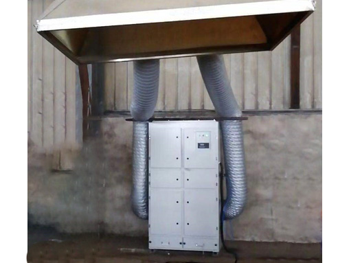
3. When installing the suction fan, the operator is strictly prohibited from reaching over the motor to clean up waste.
4. It is strictly prohibited to wear slippers during work to avoid hitting feet with molds, iron blocks, etc. in the workshop. The class monitor, fitter, and mold repairman must wear safety shoes when going to work;
5. Male operators are strictly prohibited from keeping long hair, while female operators should tie up their long hair to prevent it from getting caught in the flywheel.
6. Pay attention to other oils such as white oil, alcohol, cleaning agents, etc.
7. When packing materials, waste, and molds, gloves should be worn to avoid scratching hands.
8. When there is oil, it should be cleaned in a timely manner to avoid slipping and falling.
9. It is strictly prohibited to wear gloves when drilling and milling machines; Wear a mask and eye protection when using the grinder to protect yourself.
10. Pay attention to dragging the mold to prevent it from falling to the ground (the flatbed truck must be lowered to transport the mold).
11. Non electricians are strictly prohibited from connecting electricity and repairing machines.
12. It is strictly prohibited to aim the air vent at people, as it may harm the eyes.
13. Operators need to wear earplugs.
14. When abnormalities are found in the machine, turn off the power first and then promptly seek assistance from the on duty technician. Unauthorized handling is not allowed.
When new employees start work, the team leader should explain the operating procedures to them and study them once a week every day.
16. When adjusting the machine, it should be adjusted to a single action and it is strictly prohibited to use a linked discharge belt.
17. No flammable or explosive materials should be stored under the electric switch.
18. Operators are strictly prohibited from chasing or hitting in the workshop to avoid falling, knocking over products, or injuring themselves.
19. Conduct equipment inspection according to the inspection content on the equipment inspection card, paying special attention to whether the guiding and braking devices of the punching machine are operating normally, and whether the single punch and continuous punch functions are clear.
20. When installing the die on the small punch for the automotive stamping parts, first loosen the locking device of the guide rail, install the upper and lower dies, and then adjust the travel of the guide rail until it meets the requirements and locks the fastening device. In addition, when the high punch is used to mount the die, the single stroke must be hit. After the upper die is locked, the lower die is locked after the oil pressure locking, and another inspection is made before production.
21. When discharging or manually picking up raw materials, the tools (pliers, hooks) that must be used are strictly prohibited from manually feeding or picking up raw materials. Single switch may hurt hands, dual switch is needed. The machine cannot leak oil, otherwise it will fall off. Do not expose the power supply, it is dangerous.
22. When stamping iron sheets, wear gloves and concentrate, otherwise your hands will be injured.
23. During work, first check if there are any abnormalities in the operation of the equipment, such as unclear single or continuous flushing, ineffective operation, or electrical faults. Stop the machine immediately and seek timely assistance from the on duty technician.
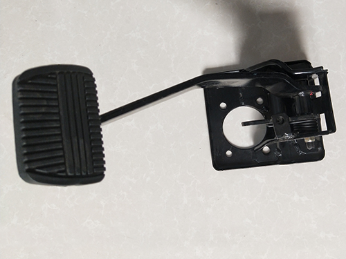
24. It is strictly prohibited to use foot switches on punching machines, and all original equipment on the machine must be removed.
When cleaning and inspecting equipment, the power must be cut off before operation.
26. Cut off the power, clean and scrub the workbench, remove the mold for maintenance and storage, and check the lubrication system oil every week.

